
(c) Mousetrap, 2004
A quick summary of the process for manufacturing electronic products is this: components are placed on a
PC board and soldered to the PC board (sometimes done a second time), the resulting assembly is run
through In-Circuit Test (ICT), and then through Functional Test (FT).
ICT is quite well defined and understood. It checks for, among other things, shorts, opens, wrong
component values, components inserted backwards. These checks are critical, and any UUT that passes
ICT SHOULD function, but a pass does not indicate that the UUT will function CORRECTLY (as per spec.).
FT is less well defined. Use an internet browser to search for “Functional Test”, then start looking at the
results. Many of the sites found treat FT as treating the UUT as a closed box and testing the inputs and
outputs, or treating it as a PCBA and also testing a few critical internal circuits. Some of the sites treat FT
as testing the functionality of the individual circuit components; essentially a level above ICT. Sometimes,
FT is just treated as powering the UUT on, loading code, and maybe configuring it.
As a practical matter, and in Mousetrap’s experience, functionally testing the individual circuit components
is usually unnecessary for commercial products, and rarely cost effective. There are exceptions. Loading
and configuring code is not FT, although they are critical, are usually done at FT time, and are therefore
usually assumed to be part of FT.
Why Bother to Test?
A number of magazine articles, white papers, and other sources (you did the search, right?), indicate that
ICT and/or FT are quickly becoming unnecessary, or not doable. Increasingly-fine pitch components,
decreasing component size and increasing component density do indeed make probing more difficult.
Large ICs cover more traces, preventing access. ICT can’t be done.
There are many digital design engineers who get the design right the first time every time. Some even
design the original board to have test points brought out on break-away boards; once the board has been
through production and tested, the test point boards can be broken off, as they will never be needed again.
ICT and FT aren’t needed.
Even if the designer always gets it right, components sometimes get put in backwards, or are not
completely soldered down. Sometimes the wrong component, or wrong value, is installed. Sometimes,
there are shorts. If the UUT has $1000 or so of components, a bone-pile of 1or more will eat a lot of profit.
Reworking a UUT, that ICT indicates has a backwards component, is cheap; reworking one that smoked
(no ICT), and smoked $250 of components, will cost much more, and get the wrong kind of attention (a
report, meetings, status). You need ICT.
The world is not all digital. In the analog world, tolerances matter. Receivers need to be tuned and
checked for sensitivity, transmitters need to be tuned and checked for power output (in-band and out-of-
band). You need FT.
Catching bad components at ICT is cheap. Catching non- or poorly-functional product, or tuning/adjusting
it, at FT is almost as cheap. Selling product that performs poorly makes money for your competitors. Paying
a spin-doctor to ask people if they can hear him is something no one wants to do. Selling product that does
not work is economic disaster. Recalling product that fails will put your company out of business. Ask
several spin-doctors if they can help you now.
What to Test
Functional Test looks at block diagrams instead of schematics, since the block diagrams indicate
functionality. In general, every input and every output should be tested. This means all of the inputs and
outputs to the box, and possibly some of the more important sections of the PCB.
There are exceptions. RAM is generally tested via a microprocessor running a POST, and maybe an
additional set of software tests, so probing is not necessary. 4-port Ethernet ports are usually connected to
an ethernet chip that controls 4 ports; if ICT passes, then the solder connections are probably good, so
testing 1 of the ports is usually sufficient. Checking the schematics should resolve this sort of question.
Generally, inputs should be tested with a variety of input stimuli that represents the expected range, outputs
should be tested to their limits.
There are exceptions here too. Testing a DSL line can be complex, or it can be as simple as testing for a
link at the maximum line length (use a wireline simulator or a lot of spools of cable). Usually, an
acceptable link rate at the maximum range is sufficient for FT. Engineering gets to test the link rate at
several ranges.
Sound vague?
Examples
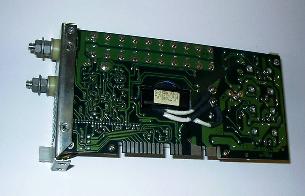
Fig. 1 is a picture of a power supply module. Most of the components are large, thru-hole, components,
and are mounted on one side. ICT looks to be straightforward. Is it necessary? Read on.
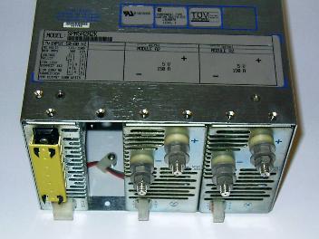
Fig. 2 is a picture of the power supply module, installed in a chassis. Look at Fig. 2 carefully; each module
is rated at 5V, 150A (this is a 1.5kw supply, requires 230VAC @ 15A).
As a side note, observe that the number of test points for FT (about 40; AC in, Controller, Ch1, Ch2, plus the
white connectors (1 “connection” but about 10 wires each) along the bottom) is very much less than the test
point count for ICT (about 90 pins, maybe more, maybe less). If this UUT had no connectors, the number of
test points would be 10.
FT equipment might be:
1. An AC Source (provides OC/OV protection, noise injection, etc.)
2. A DMM
3. Three very large (2kw) resistors, maybe 0.07 ohms, 0.034 ohms and 0.025 ohms.
A typical FT for this UUT might be:
1. Make sure all loads are disconnected (assuming this PS needs no load, some need a load)
2. Power UUT on
3. Measure voltage, ripple and noise (DMM and AC Source, log results).
4. Turn noise source on, repeat #2, turn noise source off
5. Connect medium load (75A), repeat #3, #4, disconnect load
6. Connect Max load (145-150A, repeat #3, #4, disconnect load (verify PS delivers rated current)
7. Connect Overload (160A), repeat #3, #4, disconnect load (see manufacturer’s directions)
8. Connect Short, repeat #3, #4, disconnect load (verify PS shuts down)
9. Connect medium load (75A), repeat #3, #4, disconnect load (verify PS has reset)
10. Power UUT off
Steps 5,6,7 and 8 involve potentially hazardous amounts of current, and failure modes that no one wants to
see (reading about them in an article in a trade journal might be okay). In a power supply of this size, only
one of the failure modes is acceptable (no output) during FT. ICT will help prevent the other failure modes.
None of the failure modes are acceptable to customers. Ever.
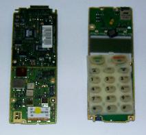
Fig 3 is a cell phone. This particular cell phone is a few years old, and is slightly larger than those available
today (but it was $5). Both boards have small, fine-pitch components on both sides. ICT is probably still
doable.
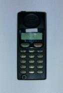
Fig. 4 is the result of assembling the boards in Fig. 3. The number of FT test points is greatly reduced; 2 for
power, 1 for the antenna, maybe 17 (solenoids) for actuating the keypad.
This UUT might be a candidate for FT initially as a PCBA (not assembled, ready to ship),for a variety of
reasons. There might be a need to verify that the initial production units have no noise issues, the values
used by the firmware to control an internal amp are correct, and loading firmware might require access to
test points on the boards. These are issues that need to be resolved in conjunction with Engineering.
FT equipment might be:
1. An DC Power Supply
2. A DMM
3. A Spectrum Analyzer
4. A cellular test station (available from several of the larger test equipment manufacturers)
A typical FT for this UUT is lengthy. Typical tests might include: keypad and display functional, software
version and configuration correct, transmitter power correct, receiver sensitivity sufficient, receiver SNR
within spec, Tx and Rx on all frequencies correct. If they can't hear you, they'll buy a different phone.
What Not to Test and Test Point Count
FT uses a small fraction of the number of test points of ICT. Using the definition of FT in Paragraph 4, too
many test points indicates something. Logic analyzers are valuable tools, but using one in FT is usually an
indication of a problem. Same with an In-Circuit Emulator (ICE).
Some years ago, a Mousetrap employee wrote a functional test program for a customer’s VME board, one
with a lot of RMAs. The test included VME bus control. A consultation with Engineering added about 100
test points, all in the digital section. It seems that the board would periodically generate a bus fault.
Running the tests several times eventually showed, with the help of a logic analyzer, that the board would
occasionally fail (DTACK remained asserted).
This sort of testing is important, but it belongs in Engineering, or Rework, not in Manufacturing Production.
If you did the search (paragraph 3, remember?), industry trends (“Why Bother to Test?”) indicate that FT for
digital boards is unnecessary. This isn't exactly true, but it is an indicator. Most digital sections should be
correct before the board is released to production. An excessive number of test points in the digital or
microprocessor section (not digital I/O test points) usually points to a board not ready for sale.
Estimating the number of test points for a generic board is tough, without having a board to examine, but
some general guidelines are available.
1. Count the number of external connectors. These include power, ethernet, USB, PCMCIA slots, etc.)
2. Determine how each connector will be tested. (1 connector may have many wires)
AC Power is usually 3 wires, and even though 1 connector can be used, switching power via relays will
take 2 relays (2 wires to control). DC power can be done with 1 wire.
PCMCIA slots can be tested by using a “known good” card, maybe a serial card with an external loopback
cable, and sending a loopback message. Many wires, but only 1 thing to control: 1 “wire”.
3. Figure out the number of wires involved. This gives a rough indication of test point count.
4. Check the schematics for any internal analog circuitry that is controllable, or sensitive. An on-board
amplifier that is controlled via a microprocessor is a good candidate. Measuring the amp input and
output with a scope, while varying the gain by a known amount, is a good test. 2 more test points, plus
software.
5. Check for any digital signals that need to be monitored. Counting pulses, measuring pulse length,
measuring the time between pulses on different lines, triggering off of a digital line are frequently done. If
you’re doing the same test again and again, it should be for some sort of Digital I/O system. Are you
using a logic analyzer? This might be an Engineering test, not Functional Test.
6. Review the results. If the Functional Tester will only be used for production, then the cost of doing
Engineering tests will cut in to Manufacturing Capacity. If the Functional Tester will be moved to do
Debug/Rework, then the Engineering tests will be quite valuable.
Multiple UUTs
In many cases, testing more than 1 UUT at a time can yield considerable cost reductions and time
savings. This is because many operations can be done simultaneously, or at least in a heavily pipelined
manner. Several UUTs can be powered-on in slightly more time than the time needed to power-on one
UUT. Instrument setup time can be divided up among several measurements instead of just one. Code
load, if done through an ethernet switch , is almost a parallel operation.
The drawbacks to this approach are that the time to load and unload the UUTs will be longer, and many
relays will be needed.
The advantage, however, is production throughput.
As a first-cut design, assuming one power supply and independent power relays to connect and disconnect
power to each UUT, if powering-on and booting 1 UUT takes 20 seconds (2 sec. current in-rush), 8 UUTs
could be done in (7x2 sec.+20 sec, last unit) 34 seconds. The time needed increases by 70%, but the
throughput increases by a factor of 8. The overall efficiency increases about 300%.
If each UUT draws 1.0A in-rush, then settles down to 250mA, then booting 8 UUTs (1 UUT every 2 sec)
would yield a maximum current drain of about 3.0A from the power supply before settling down to 2.0A.
Power supplies rated at 5.0A (5V, 30V, ...) aren't too hard to find. Booting 8 UUTs at the same time yields an
8.0A current drain, and this is at least the next level (10.0A) of power supply, maybe another level
considering that 8.0A is a lot of in-rush current for a 10.0A power supply.
Another advantage to pipelining the power-on operation is that, if the power supply is monitored, if one unit
shorts, it is easily identified. Booting the units in at the same time makes identification more difficult. If one
unit merely draws excessive current, shutting it off without affecting the other units is usually possible so
testing on the other units may continue..
Some instruments can be setup to make a measurement quickly (a second or so). Others, usually high-
end instruments, like a 40 GHz oscilloscope, may take 10 seconds to configure for a measurement. The
time to make a measurement is unavoidable, but the repeated instrument setup time is. If a 10 second
instrument configuration is needed, better to do it once, then make as many measurements as possible
before reconfiguring the instrument. In this example, 70 seconds of repeated instrument setup will be
saved.
Tests that must be done sequentially yield small increases in efficiency, They save instrument setup time,
not much else, but are generally worth doing.
Tests that can be done in parallel yield large increases in efficiency. Sometimes, one or two parallel test
steps (2 code downloads) are all that is needed to make the FT effort pay for itself in 2-4 weeks of
production.
Tests that can be pipelined (power-on) can also large increases in efficiency. This is one area where the
test engineer has to earn his money.
General increases in efficiency are difficult to predict in the absence of a specific example, but empirical
evidence, and experience, indicate that dividing the number of UUTs to be tested by 2, then subtracting
10%, yields an approximate value for the throughput increase.
6 UUTs might take 2.7 times the amount of time it takes to FT 1 UUT. This is about twice as efficient.
As expected, as the number of UUTs increases, the load and unload times become important, and the
increase in efficiency declines (it still increases, but not by much. 64 is more efficient than 8, but is it worth
the effort?).
Note that these numbers are heavily dependant on the ratio of time spent doing parallel or heavily pipelined
tests to the time spent doing sequential or slightly-pipelined tests. A lot of sequential tests will show very
little gain.
Instrument Selection
Functional Test is rather simple if the only measurements to be made involve (low) voltage, frequency,
pulse count, pulse timing, code load and configuration, and then high level functionality (an ethernet ping, a
link to a DSLAM, etc). A few generic instruments (a good DMM, oscilloscope, a counter-timer board, a
power supply) should do. This looks like a standard bench suite of instruments.
As the tests become more specialized, the instrument requirements rapidly become more specialized.
Instrument selection them becomes driven by the tests to be performed. Costs increase, and this is
unavoidable. A GPIB card makes it possible to control the needed equipment.
The Bottom Line
Functional Test is a bit of an art. The UUT drives test point selection, test selection, and instrument
selection.
test fixtures, test fixturing, manufacturing test, production test, boundary scan, fixtures, fixturing