
If you need to do Functional Test, why not use a Functional Test System?
PC Board Debugging, Functional Test / Calibration and Rework is one of those
things that takes a lot of time; a lot of setup time, connection time, pin-counting
time, etc.
A little a fixture, to create a little factory automation goes a long way. A functional
test system can make a big difference for production and your economic bottom
line.
to the time.
Using a fixture, some instruments and a PC to run a test program is a tremendous
time saver, and produces repeatable results. Just put the board in the fixture,
press the "Test Me" button, and wait for some data. Then do any manual examination,
as needed.
A little factory automation makes testing, debugging, repairing, etc., very much easier.
Initial cost reduction happens quickly and with very little effort..


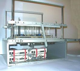
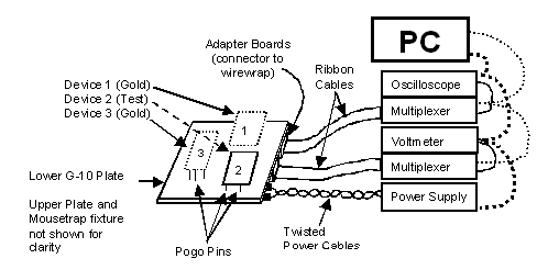
shows the pogo-pins and
edge guide pins installed in
the lower Cartridge plate.
The Cartridge is available
as a blank (you do the
drilling), or drilled to your
specifications (from your
Gerber files).
Just about any machine
shop can do the drilling.
Optimizing the layout is the
only tricky part (see below)
Everyone has a modem, so everyone understands modems.
The test points selected are: POWER, LINE and LINE OUT (the phone
connections), the DB-25 (connects to the PC), the speaker, the LEDs and the
2 crystals. Total pogo-pin count, 30 pins per modem.
These modems are large enough so 4 will fit easily, and leave space for the
connector block (see below).
The connector block is attached to the Cartridge plate, and holds various
boards that connect external cables to the wirewrap that is attached to each
pogo-pin.
Usage is simple:
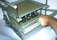
Step 1. Load the UUTs into the Mousetrap (ground strap is on the Left hand)
Step 2. Close the Mousetrap
Step 3. Run tests / start debugging (The time savings will become apparent)
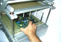
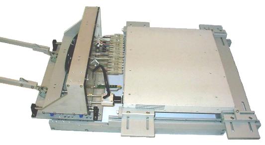
In this example, the Cartridge top plate only has hold-down pins (the white
rods), as all test points are accessible from the bottom. Using shorter hold down
pins and adjusting the Mousetrap allows pogo-pins to be used from the top as
well. The advantage to the longer hold down pins is photographic (good
pictures), and more access for manual probing from the top. Adding a few
access holes to the top plate is all that is needed, and this can be decided at
layout time.
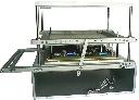
loaded and closed Mousetrap. The
cable connectors are visible just above
the Gold Modems.
The cable connectors are mounted on
the Cartridge.
Using modems to talk to other modems
is a typical functional test technique
(this is Functional Test, so money is
always tight). The Gold Modems are
mounted on a removable tray
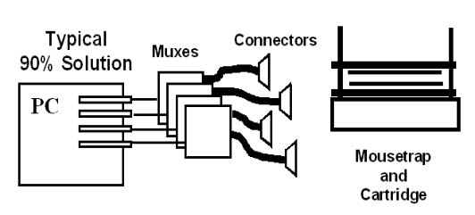
The Mousetrap as part of
The 90% Solution.
This system can be built
for Engineering, put on a
cart and moved to
Manufacturing and used
for NPI/LPR Functional
Test / Manufacturing Test
and Rework of bad units.
No additional charge.
The money you spend
once keeps working.
If your product changes,
rework your functional test
software, and perhaps buy
a new Cartridge
Providing Factory-level
support to the field is
now easy.
This is essentially one level up from PC board testing.
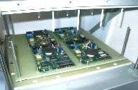
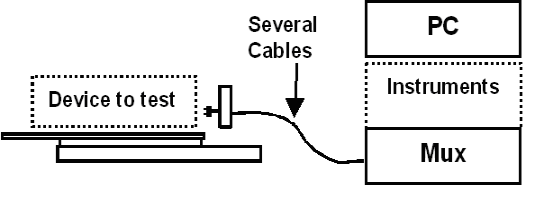
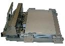
Sometimes, functional test of a closed box is necessary or desirable. In fact, the unit
shown was sent to functional tested as a closed box.
answer to such needs.
Sometimes, the unit has
enough internal diagnostics
to provide most debugging
/calibration needs.
If necessary, the box may
be opened, for manual
probing for rework/debug.
The adjustable stops may
be replaced with a plate of
G-10, customized for the
specified unit. This photo
looks better though.
Do you use Boundary
Scan? Perhaps 8 or 16
port equipment?
Customise the Drawer plate
to hold 8 or 16 boundary
scan connectors; machine
a delrin block to hold your
boards, and you have
instant mass connections
for Boundary Scan.
fixtures, test fixturing, manufacturing test, production test, boundary scan, fixtures, fixturing